
Fiber optic testing, splicing, and repair should restore a documented connection and verify the systems that depend on it.

Start with commercial fiber infrastructure planning for backbone design.
This guide focuses on diagnosing a fault, defining the repair, and checking the completed result with IT and facilities staff.
Start with the Affected Service
Record what stopped working and when. Identify the buildings, remote switches, cameras, or other equipment affected. Note recent work near the cable route or equipment cabinets. A failed connection may involve cabling, optics, power, patching, or configuration, so the symptom should guide the investigation rather than an assumption that the fiber is broken.
Collect the route drawing, strand schedule, previous test results, and equipment records. Name the contact who can authorize an outage and the team that will confirm service restoration. If a shared backbone carries several systems, agree on priorities before disconnecting it. Include any temporary operating arrangements that the site needs during the investigation.
Inspect the Path and Establish a Baseline
A qualified technician can compare the current condition with the installation record. Identify the endpoints and patching before disturbing a working circuit. Inspect accessible connectors, enclosures, and cable routes using appropriate equipment and procedures. Keep connector cleaning and inspection under the test plan; contamination can complicate measurements and damage connections.
The owner’s role is to supply access and operational information, not to look into fiber ends or attempt an improvised splice. Active optical systems require appropriate handling. A service request should identify any restricted areas, elevated work, outdoor routes, and other site conditions so the work can be planned safely.
Choose the Right Fiber Test
Optical loss testing evaluates the defined end-to-end fiber path. OTDR testing helps locate and characterize events along a route. Inspection addresses connector condition. The test plan should distinguish these tasks and identify the fiber type, test configuration, wavelengths, and acceptance criteria. Use suitable test equipment and compare results with the existing baseline where available.
The Fiber Optic Association testing guide explains the role of installed-fiber measurements.
Fluke Networks Versiv can support these tasks through the appropriate modules.
CertiFiber Pro and OptiFiber Pro serve different measurement roles; specify the required method rather than treating any instrument result as interchangeable.
Use OTDR Findings to Guide the Investigation
An OTDR trace can help identify an event near a connector, splice, bend, or apparent break. Interpretation depends on the equipment setup and the characteristics of the link. Compare the trace with documented route features before deciding where physical work is needed. A distance shown on a trace is not a substitute for locating the actual cable route on site.
Preserve the original trace, the diagnostic findings, and the final test record. If more than one strand shares the damaged section, identify which strands were checked and which remain untested. Do not report the entire cable as restored based on a single working circuit.
Define Fusion Splicing and Repair Scope
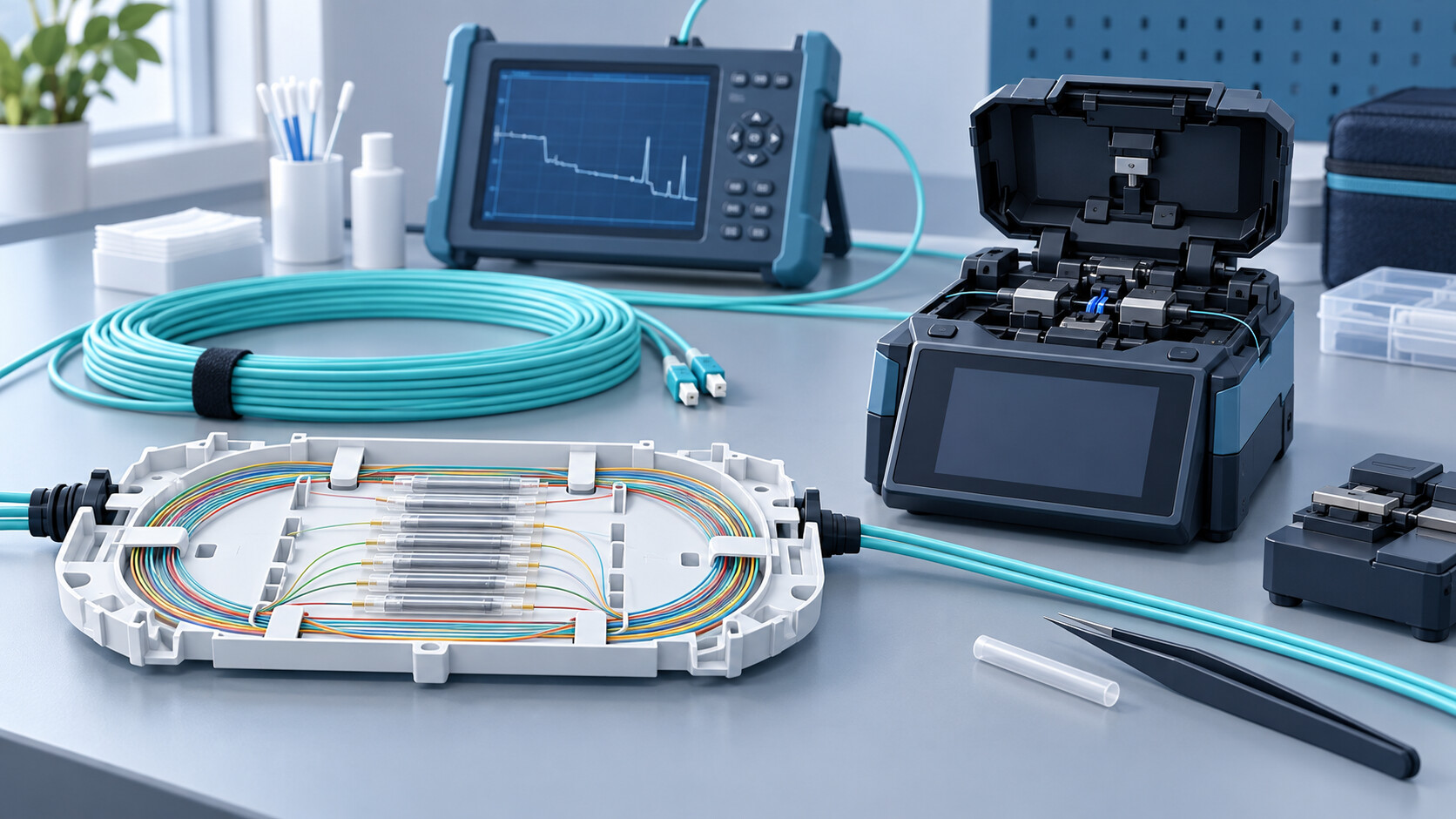
Fusion splicing joins prepared fiber ends, with the completed joint protected and organized in an appropriate tray or closure.
The work needs compatible fiber, suitable equipment, controlled preparation, and enough usable cable to complete the repair.
The FOA fusion-splicing reference provides background on the process and equipment considerations.
A repair is more than the splice itself. Check the condition of the damaged section, available slack, enclosure, strain relief, and routing. The written scope should identify whether the work replaces a patch cord, reterminates an end, repairs a splice, or replaces a damaged section. Record any constraints that may make a temporary restoration necessary.
Do not use a splicer’s estimated loss as the sole proof that the completed link meets the project requirement. Test the restored path using the agreed method and retain the result. If the final result fails, investigate the complete path rather than assuming the newest splice is the only possible cause.
Temporary Restoration and Permanent Repair
During an outage, the owner may prioritize a limited set of services.
Document which circuits are restored first and any reduced capacity or temporary route.
The FOA restoration guide emphasizes preparation, records, and the distinction between restoring service and completing a permanent repair.
Give temporary work a named owner and a completion plan. Update the site record when the permanent arrangement replaces it. Do not leave the next support team to discover an undocumented bypass during a later outage. Confirm access requirements and operating windows before scheduling the final change.
Retest and Confirm the Application
After repair, compare the measured result with the agreed acceptance criteria. Save the affected strand identifiers, endpoints, test conditions, and reports. Update the splice schedule and route notes where they changed. Retain enough information to distinguish the pre-repair condition from the restored baseline.
Then ask the system owner to confirm actual operation. A remote switch should reconnect as intended; cameras should record and play back; other dependent systems should complete their normal tasks. Review alarms or error logs that remain active. A restored optical path and a restored business service are related but separate checks.
Records That Make the Next Repair Easier
Maintain a current strand schedule, endpoint labels, enclosure locations, and test results. Record spare strands separately from active circuits. Keep equipment and optics information with the route record, and assign responsibility for updating it after moves or additions. Store a copy where the owner can retrieve it during an outage.
For report requirements, use the copper and fiber certification guide.
For the wider project, infrastructure planning coordinates power, cabinets, network ownership, and connected systems.
Frequently Asked Questions
Does an outage always mean the fiber needs splicing?
No. Patching, connectors, optics, power, or configuration may be involved. Diagnose the affected path before choosing the repair.
Can an OTDR result replace optical loss testing?
The methods serve different purposes. Follow the project’s acceptance specification and retain the required loss results and diagnostic traces.
What should I provide when requesting fiber repair?
Provide the site location, affected services, timing, access constraints, available route records, and outage contact. Describe symptoms without assuming a cause.
Request a Fiber Infrastructure Assessment
Contact NERSA through the assessment form to define fiber testing, splicing, repair, or upgrade requirements for your commercial property.
Confirm scheduling and the written scope for the specific site.