
Commercial and industrial video surveillance installation turns a facility’s coverage plan into a working system, with cameras positioned to capture the detail staff need.

Request a commercial video-surveillance installation assessment
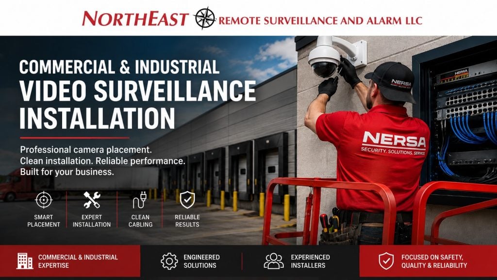
Northeast Remote Surveillance and Alarm, LLC installs commercial IP camera and CCTV systems for warehouses, manufacturing plants, distribution facilities, office buildings, healthcare properties, schools, municipal facilities, industrial sites, contractor yards, commercial campuses, and multi-building organizations.
A professional installation accounts for camera purpose, target distance, viewing angle, mounting surface, lighting, weather, vibration, cable pathways, network capacity, recording equipment, service access, employee and vehicle movement, and the conditions that will exist after the property closes.
This guide covers camera placement, physical installation, cabling, mounting techniques, aiming, commissioning, and final system handoff.
For platform selection, recording architecture, analytics, system applications, and broader camera-system planning, visit our commercial and industrial video surveillance systems resource.
Commercial and industrial systems only • New installations • Professional camera placement • Clean mounting and cabling • Small business through enterprise
Professional Camera Installation Begins Before the Camera Is Mounted
The most important installation decisions are usually made before the first hole is drilled.
A commercial site review should identify what each camera must accomplish, where the subject will be located, how people or vehicles will move through the scene, what lighting will exist during operating and closed hours, and how cabling will reach the final mounting point.
The installation plan may document:
- Camera purpose
- Target area
- Expected subject distance
- Required level of detail
- Proposed mounting height
- Camera direction and field of view
- Mounting surface
- Cable pathway
- Network or recorder destination
- Required lift or access equipment
- Daytime and nighttime lighting
- Weather or environmental exposure
- Service and maintenance access
- Nearby structures that may obstruct or reflect light
- Future construction or equipment changes
A useful camera schedule gives each device a clear name and objective rather than treating the entire project as a camera count.
Examples include:
- Main Entrance – Facial Identification
- Warehouse – Dock Door 12 Overview
- North Lot – Vehicle Exit
- Shipping Office – Transaction View
- Employee Entrance – Access-Control Event View
- Production Area – Line Three Overview
- East Gate – Driver and Vehicle View
Clear objectives allow the installer to choose the appropriate position, lens, mounting method, and image settings for the actual scene.
Camera Placement Based on the Required Result
Camera placement should begin with what the customer must be able to determine from the footage.
A camera intended to show that activity occurred has a different placement requirement from a camera intended to identify a person, read a license plate, document a delivery, or generate dependable analytic events.
Overview Camera Placement
Overview cameras show movement and context across a larger area.
They may be installed to cover:
- Parking lots
- Warehouse floors
- Production areas
- Loading zones
- Lobbies
- Exterior yards
- Building approaches
- Common areas
- Truck courts
- Broad perimeter sections
An overview view can show how an incident developed, which direction someone traveled, or where a vehicle moved, but it may not provide enough detail to identify every person, object, or license plate within the scene.
The installer should avoid making the field of view wider than necessary because every additional foot of scene width reduces the detail available on each subject.
Identification Camera Placement
Place identification cameras where people naturally approach, pause, pass through a controlled opening, or follow a predictable path.
Common identification points include:
- Main entrances
- Employee entrances
- Visitor vestibules
- Shipping-office doors
- Reception points
- Restricted-room entrances
- Turnstiles
- Gate intercoms
- Narrow corridors
- Controlled interior doors
An identification camera should generally be positioned to capture a useful facial angle instead of an excessively steep top-down view.
Mounting the camera as high as possible may protect it from tampering, but it can also reduce facial detail by recording mostly the top of a person’s head. The final position must balance identification, physical protection, field of view, and service access.
Transaction and Process Camera Placement
Some cameras must document an activity rather than simply show a room.
Examples include:
- Shipping and receiving transactions
- Driver check-in
- Package handoff
- Cash-handling positions
- Tool issuance
- Inventory transfer
- Production stations
- Loading and unloading
- Pallet movement
- Controlled storage access
Aim these cameras at the activity area as well as the doorway leading into it.
An overview camera may establish context while a closer camera documents the person, package, item, transaction, or work process involved.
Vehicle Camera Placement
Position vehicle cameras around the route vehicles actually follow.
Planning may consider:
- Lane width
- Direction of travel
- Expected stopping position
- Vehicle speed
- Camera distance
- Entry and exit direction
- Headlight exposure
- Sun position
- Gate equipment
- Intercom location
- Truck or passenger-vehicle height
- Potential lane changes
- Tailgating paths
A vehicle overview camera can document make, color, direction, and general activity, while a separate dedicated camera may be required when reliable plate capture is important.
A wide parking or gate overview should not automatically be expected to perform as a license plate camera.
Camera Placement for Video Analytics
Cameras intended to support people detection, vehicle detection, line crossing, restricted-area alerts, or perimeter analytics require stable mounting, clear sight lines, appropriate scene depth, adequate contrast, and carefully defined detection areas.
The installer should account for:
- Camera tilt
- Target size at the far end of the scene
- Vegetation
- Shadows
- Headlights
- Rain and snow
- Reflections
- Flags and moving signs
- Gates and fences
- Objects that may conceal people or vehicles
- Vibration
- Normal employee or vehicle traffic
Configure analytics after the camera reaches its permanent position and the customer approves the final field of view.
Camera Placement at Commercial Entrances
Entrances frequently require more than one camera objective.
A complete entrance may need:
- A facial identification view
- A wider vestibule or lobby overview
- A view of the exterior approach
- Video associated with access-control activity
- Coverage of visitor interactions
- A view of packages or items carried through the door
- Documentation of the door remaining open
The identification camera should be positioned around the path occupants naturally follow rather than aimed broadly across the entire lobby.
Glass entrances require additional attention because exterior daylight, interior lighting, reflections, headlights, and changing sun conditions can affect image quality.
Camera placement should also avoid conflicts with door movement, automatic operators, signage, architectural finishes, fire alarm devices, exit hardware, and service access.
Parking Lot and Pedestrian Camera Placement
Parking areas often require several different views because one high, wide camera cannot provide useful evidence everywhere.
A parking-lot installation may combine:
- General lot overviews
- Building-entrance cameras
- Pedestrian walkway views
- Vehicle entrance and exit views
- Accessible parking coverage
- Employee parking coverage
- Visitor parking coverage
- Loading-zone cameras
- Rear-building approaches
- Dedicated vehicle-detail views
Camera positions should follow the routes people and vehicles actually use.
The installer should consider light poles, building lighting, tree growth, signage, parked trucks, seasonal landscaping, snow piles, trailers, and other objects that may obstruct the field of view later.
Exterior cameras should not be aimed unnecessarily toward the sky because excessive sky within the image can affect exposure and reduce useful detail in the ground-level scene.
Loading Dock and Shipping Camera Placement
Loading docks combine trailers, drivers, employees, forklifts, packages, overhead doors, changing light, and moving obstructions.
A loading-dock installation may require separate views for:
- Trailer position
- Dock-door activity
- Driver interaction
- Personnel entrances
- Shipping-office transactions
- Pallet movement
- Forklift travel
- Exterior approach
- Overhead-door activity
- Yard context
Position cameras so ordinary trailer placement does not block every important view.
An exterior dock camera mounted directly behind the expected trailer position may become useless whenever a truck backs into the bay. A side or elevated angled view may preserve more usable context, while a closer interior camera may document loading activity.
Review dock lighting during and after operating hours. Open overhead doors can create extreme differences between bright exterior light and darker interior areas.
Warehouse and High-Bay Camera Installation
Warehouses commonly involve long distances, high ceilings, changing rack layouts, elevated mounting points, forklifts, suspended utilities, and limited service access.
Installation planning may include:
- Main warehouse overviews
- Cross-aisle views
- Long aisle views
- Dock areas
- Overhead doors
- Employee entrances
- Shipping and receiving
- Inventory cages
- Tool or maintenance areas
- Office-to-warehouse transition doors
- Remote corners
- Mezzanines
- High-value storage
A long aisle camera may show movement but provide limited facial detail at the far end. Cross-aisle or choke-point placement can provide additional evidence where employees and equipment pass through narrower, predictable locations.
Keep cameras and cabling clear of forklift routes, movable racks, cranes, conveyors, heating equipment, sprinklers and lighting. Allow for future storage layouts, too.
High-mounted cameras should remain reachable through an identified service method. A position that requires unusual access equipment for every adjustment, cleaning, or replacement may create unnecessary long-term service cost.
Manufacturing and Industrial Camera Installation
Industrial environments require installation methods selected around the actual operating conditions.
The site may include:
- Dust
- Heat
- Moisture
- Washdown activity
- Vibration
- Machinery
- Electrical interference
- High ceilings
- Moving cranes
- Welding
- Vehicle exhaust
- Chemical exposure
- Outdoor production areas
- Restricted processes
- Continuous operation
Attach camera mounts to stable structures. Avoid vibrating equipment, flexible panels and surfaces that move with nearby machinery.
Where dust, moisture, corrosion, impact, or temperature is a concern, the selected housing, connector protection, junction box, mount, cable, and pathway should be appropriate for that environment.
Coordinate installation with production schedules, equipment shutdowns, employee movement, material handling and approved safety procedures.
Vehicle Gates and Controlled-Lane Installation
Gate cameras should be placed according to the geometry of the entrance rather than attached wherever power happens to be available.
The installation may include:
- Driver identification
- Vehicle overview
- Dedicated plate capture
- Gate-position verification
- Intercom activity
- Credential-reader activity
- Entry direction
- Exit direction
- Tailgating review
- Delivery documentation
The camera should account for where the vehicle will stop, where the driver will be positioned, and whether trucks and passenger vehicles use the same lane.
A camera built into an intercom station may provide a useful close view of the driver but may not show the complete vehicle or surrounding activity. Separate cameras can provide the wider context.
Equipment should remain clear of gate travel, counterweights, safety devices, operator mechanisms, vehicle impact zones, and areas where service personnel must work.
Perimeter, Yard, and Exterior Storage Placement
Perimeter cameras should be installed to create clear, stable views along likely approach paths, fence lines, gates, stored equipment, rear entrances, and areas where unauthorized activity is most likely.
The installer should consider:
- Fence height
- Fence posts and mesh
- Terrain changes
- Vegetation
- Adjacent roads
- Neighboring properties
- Headlights
- Exterior lighting
- Weather
- Stored vehicles
- Trailers
- Equipment movement
- Seasonal changes
- Expected detection distance
A camera aimed along a fence may provide more useful depth than a camera pointed directly at a short section of fence, but the final position depends on the required event and site geometry.
Trees, flags, tall grass, loose materials, and other moving objects should be kept outside important analytic zones whenever practical.
Office, Reception, and Restricted-Area Placement
Office installations should provide useful entry and common-area documentation without placing cameras indiscriminately.
Common locations include:
- Main entrances
- Reception areas
- Visitor lobbies
- Employee entrances
- Parking approaches
- Shared corridors
- Delivery doors
- Server-room entrances
- Records-room entrances
- Cash-handling points
- Common areas
- Rear and side doors
Cameras should avoid areas where individuals reasonably expect privacy and should be positioned according to the organization’s legitimate security and operational policies.
Restricted-room cameras are often most useful when aimed at the entrance and surrounding approach rather than placed inside a small room with an unnecessarily broad view.
Wall, Ceiling, Pendant, Corner, and Pole Mounting
The mounting method should match the viewing objective, structure, environment, and camera model.
Wall Mounting
Wall mounts are commonly used for exterior building views, entrances, loading docks, parking areas, gates, and interior locations where ceiling mounting is impractical.
Select anchors and fasteners for the actual wall construction, such as masonry, concrete, structural steel, wood framing or another approved substrate.
The installer should not rely on thin fascia, decorative cladding, gutters, loose panels, or unsupported finishes to carry the camera and mount.
Ceiling and Soffit Mounting
Ceiling or soffit mounting can provide clean interior and exterior installations when the surface offers proper support and an appropriate field of view.
Suspended ceiling grid should not be treated as structural support for camera equipment unless an approved independent support method is used.
Check exterior soffit locations for infrared reflection, water entry, insects, service access, heat buildup and obstructions at the building edge.
Pendant Mounting
Pendant mounts may lower a camera from a high ceiling or structure to improve viewing angle, identification detail, and serviceability.
A pendant should remain stable and should not sway from airflow, vibration, nearby machinery, or building movement.
Corner Mounting
Corner mounts can support wide exterior or interior coverage around building intersections, parking areas, yards, and warehouse corners.
The mount should be positioned so the building itself does not obstruct one camera sensor or create excessive infrared reflection.
Pole Mounting
Pole-mounted cameras can support parking, gate, yard, roadway, and perimeter views where the building does not provide an appropriate location.
Pole installations may require:
- Suitable pole structure
- Secure equipment cabinets
- Protected pathways
- Fiber or engineered wireless connectivity
- Surge planning
- Grounding coordination
- Weather-resistant connections
- Service access
- Lift access
- Wind and vibration consideration
The camera should not be mounted on a pole that moves excessively under normal wind or traffic conditions.
Parapet and Rooftop Mounting
Parapet or rooftop mounting may be considered when other positions cannot provide the required view.
The design should account for roof integrity, weather sealing, wind, lightning exposure, service safety, cable pathways, roof access, and the effect of a steep downward angle on identification.
A rooftop position should not be selected merely because it is the highest point available.
Exterior Weatherproofing and Cable Entry Techniques
Outdoor camera reliability depends heavily on the connections and pathways behind the camera.
An exterior installation may use:
- Weather-resistant junction boxes
- Suitable cable glands
- Protected connectors
- Outdoor-rated pathway materials
- Drip loops
- Sealed building penetrations
- Protected service loops
- Manufacturer-compatible mounts
- Corrosion-resistant hardware
- Surge-protection measures where appropriate
Arrange cable entries to shed water away from the enclosure.
Connectors should not be left exposed behind a camera or wrapped as a substitute for a proper enclosure. Moisture can travel through an inadequately protected connection and damage the cable, camera, switch port, or connected network equipment.
Exterior penetrations should be sealed through methods appropriate to the wall, roof, enclosure, and applicable building requirements.
Position cameras with built-in infrared illumination away from surfaces that can reflect infrared light directly back into the lens.
Commercial Camera Cabling and Pathway Installation
Plan camera cabling as permanent commercial infrastructure.
The installation may include:
- Category cabling
- Fiber-optic cable
- Conduit
- Cable tray
- J-hooks or other approved supports
- Surface raceway
- Equipment cabinets
- Patch panels
- Wireless bridges
- Underground pathways
- Building-to-building links
Cable routes should avoid sharp edges, crushing, excessive pulling force, unsupported spans, heat sources, moving equipment, and conditions that may damage the cable later.
Low-voltage pathways should be coordinated with electrical, fire alarm, mechanical, structural, and other building systems according to applicable requirements.
Label every cable at both ends with a consistent camera or location identifier.
Use termination components compatible with the selected cable. Test the completed connections before final system acceptance.
Ethernet Distance, Fiber, and Remote Camera Locations
Standard copper Ethernet channels are generally limited to approximately 328 feet or 100 meters, including patch connections.
Where the route exceeds that distance, the installation may require:
- A remote network switch
- Fiber-optic backbone
- Additional network cabinet
- Engineered point-to-point wireless bridge
- Another approved transmission method
The correct choice depends on distance, available power, building separation, bandwidth, environmental exposure, service access, electrical conditions, and future expansion.
Fiber is often appropriate for long links, detached buildings, remote network closets, gatehouses, parking structures, and large commercial campuses.
A wireless bridge should be treated as engineered infrastructure rather than a consumer Wi-Fi extension. Confirm line of sight, mounting stability, interference, bandwidth, power, weather exposure, security and alignment.
PoE Switch and Camera Power Installation
An available network-switch port does not necessarily mean the switch has enough power to support another camera.
PoE planning should account for:
- Camera power requirement
- PoE standard supported
- Per-port capability
- Total switch power budget
- Startup demand
- Outdoor heaters
- Infrared illuminators
- Multi-sensor cameras
- PTZ motors
- Cable distance
- Backup power
- Future camera additions
The switch should include reasonable capacity beyond the immediate connected load so normal startup conditions and future changes do not create unstable devices.
PoE switches should be installed in secure, ventilated, serviceable locations rather than left on shelves, placed above ceilings without access, or connected through undocumented temporary power arrangements.
Recorder, Server, and Equipment-Rack Installation
Recording and network equipment should be placed where it can operate reliably and be serviced safely.
The equipment location should provide:
- Physical security
- Controlled access
- Ventilation
- Appropriate temperature
- Stable power
- Backup-power capability
- Network connectivity
- Cable management
- Service clearance
- Room for expansion
- Protection from water and impact
- Clear equipment labeling
Recorders and servers should not be placed automatically in hot attics, damp utility spaces, unlocked public areas, dusty production zones, or cabinets without sufficient ventilation.
The installation may include racks, shelves, patch panels, PoE switches, fiber enclosures, UPS equipment, cable management, recording appliances, and secure network connections.
Label equipment and cables so future service does not require tracing unidentified connections through the building.
Camera Aiming, Lens Adjustment, and Image Setup
Mounting the camera is not the end of the installation.
Aim and configure each camera for its assigned purpose.
Final setup may include:
- Pan, tilt, and rotation
- Lens adjustment
- Focus
- Field of view
- Exposure
- Wide dynamic range
- Day and night mode
- Infrared intensity
- White balance
- Shutter settings
- Frame rate
- Compression
- Privacy masks
- Image orientation
- Camera name
- Time synchronization
- Recording profile
Evaluate each camera at the subject distance and activity level expected in the finished scene.
For entrances, the installer may test a person approaching and passing through the door. For parking areas, testing may include people walking and vehicles moving under actual lighting. At loading docks, check views with overhead doors open and trailers in their normal positions.
In vehicle lanes, test headlight glare and moving vehicles under normal operating conditions. An empty daytime image cannot show these effects.
Daytime and Nighttime Image Testing
Test commercial cameras under the lighting conditions in which they need to perform.
Night testing may reveal:
- Infrared reflection
- Headlight glare
- Excessive image noise
- Motion blur
- Overexposed lights
- Dark facial images
- Spider webs or insects
- Reflections from glass or metal
- Areas outside the effective illumination range
- Obstructions not obvious during daylight
The correction may involve changing camera position, narrowing the view, adjusting exposure, changing shutter settings, moving supplemental lighting, reducing infrared output, selecting another lens, or using a more appropriate camera.
A daytime image alone is not sufficient acceptance for a camera expected to provide useful after-hours evidence.
Final Analytics Calibration
When analytics are included, calibration should occur after the camera has been securely mounted and the field of view is final.
Setup may include:
- Person detection
- Vehicle detection
- Line-crossing rules
- Restricted zones
- Loitering conditions
- Directional movement
- Camera-tamper alerts
- Recording triggers
- Event schedules
The installer should test actual movement through the scene and adjust zones to reduce events caused by roads, neighboring properties, vegetation, headlights, weather, and normal business activity.
Any later movement of the camera may require the analytic rules to be checked or recalibrated.
Installation in New Construction
New construction allows camera positions and pathways to be coordinated before walls, ceilings, exterior finishes, concrete, paving, and equipment areas are complete.
Early planning may establish:
- Camera mounting points
- Conduit
- Sleeves
- Cable tray
- Equipment rooms
- Network cabinets
- Fiber routes
- Pole locations
- Gate pathways
- Exterior penetrations
- Power requirements
- Lift access
- Spare pathways
- Future camera locations
Camera positions should be coordinated with lighting, signage, doors, gates, fire alarm equipment, sprinkler systems, mechanical systems, architectural finishes, and landscaping.
The project scope should identify the responsibilities of the security integrator, electrical contractor, general contractor, IT provider, owner, and other affected trades.
Installation in Occupied Commercial Facilities
Commercial camera installation can often be completed while the property remains operational.
Project scheduling may account for:
- Employee shifts
- Production schedules
- Deliveries
- Customer traffic
- School hours
- Healthcare operations
- Restricted areas
- Lift movement
- Ceiling access
- Network changes
- Recording cutovers
- Temporary camera outages
- Noise
- Dust control
- Work-area protection
Work may be phased by building, floor, department, exterior area, or camera group.
The customer should be informed in advance of any expected interruption to recording, remote access, network equipment, entrances, parking areas, or normal operations.
Common Commercial Camera-Installation Mistakes
Mounting Cameras Too High
Excessive height may create a large overview while reducing useful facial, package, or vehicle detail.
Aiming Too Wide
A camera that attempts to cover an entire parking lot, warehouse, or production floor may fail to provide useful detail anywhere within the scene.
Expecting Digital Zoom to Recover Missing Detail
Digital enlargement cannot recreate detail that was never recorded.
Ignoring Nighttime Conditions
A camera that looks excellent during the day may be ineffective after dark.
Placing Cameras Near Reflective Surfaces
Walls, soffits, glass, signs, license plates, and light-colored surfaces can reflect infrared light into the lens.
Mounting on Vibrating Structures
Machinery, flexible poles, moving structures, and thin panels can produce unstable video and poor analytic performance.
Leaving Exterior Connections Exposed
Unprotected connectors and cable entries can lead to moisture damage and intermittent failures.
Exceeding Copper Network Distance
Long category-cable runs can create unstable communication or power problems when the standard channel distance is exceeded.
Ignoring PoE Power Capacity
A switch can have unused ports while lacking enough total power for additional cameras.
Placing Equipment in Hot or Unsecured Areas
Recorders, switches, and power equipment require secure, ventilated, serviceable locations.
Failing to Label Cameras and Cables
Generic names and unidentified cables make investigations, administration, and service unnecessarily difficult.
Skipping Playback and Export Testing
Live video does not prove the recorder is storing usable footage or that evidence can be exported.
Skipping Customer Training
A completed installation is less useful when authorized users cannot search, play, export, preserve, or manage footage.
NERSA Commercial Video-Surveillance Installation Process
1. Facility Review
NERSA reviews the property layout, operating conditions, entrances, parking, loading areas, interior activity, vehicle movement, lighting, mounting surfaces, network spaces, and installation constraints.
2. Camera-Placement Plan
Each camera receives a defined objective, proposed location, mounting method, target area, field of view, cable route, and equipment destination.
3. Pathway and Equipment Planning
Cable types, conduit, fiber, wireless links, PoE switches, racks, cabinets, recording equipment, backup power, and lift requirements are identified.
4. Project Coordination
Installation timing and responsibilities are coordinated with the customer, IT provider, general contractor, electrical contractor, facility personnel, and other affected trades.
5. Cabling and Infrastructure Installation
Camera cabling, fiber, pathways, enclosures, racks, switches, and related infrastructure are installed, terminated, tested, and labeled.
6. Camera Mounting
Cameras are attached using mounting methods appropriate to the structure, environment, camera model, field of view, and service requirements.
7. Network and Recording Configuration
Cameras, switches, recorders, servers, user accounts, time settings, recording profiles, and approved remote-access functions are configured.
8. Final Aiming and Image Adjustment
Each camera is focused and adjusted according to its intended overview, identification, process, vehicle, plate, or analytic objective.
9. System Commissioning
Live video, recording, playback, evidence export, camera names, time synchronization, user permissions, network communication, power recovery, and applicable analytic events are tested.
10. Customer Training and Handoff
Authorized personnel receive instruction on live viewing, playback, searching, export, incident preservation, user access, and basic system operation.
What a Commercial Installation Proposal Should Define
A written proposal should clearly state:
- Camera quantities and types
- General camera locations
- Intended camera objectives
- Mounting methods
- Cabling and pathways
- Conduit where included
- Fiber or wireless connectivity
- Network-switch requirements
- Recording equipment
- Storage assumptions
- Software and licenses
- Lift and access equipment
- Remote-access scope
- Customer responsibilities
- Work by other contractors
- Expected interruptions
- Testing
- Training
- Documentation
- Exclusions
- Optional work
- Warranty terms
Two projects with the same camera count can require very different labor, mounting, pathways, switching, equipment access, and commissioning.
For additional budgeting information involving camera type, mounting height, conduit, lift access, cable length, recording, and infrastructure, review our commercial security camera installation cost resource.
Why Businesses Choose NERSA for Camera Installation
Northeast Remote Surveillance and Alarm, LLC has provided commercial security and low-voltage services since 2008.
NERSA focuses on business and professionally managed environments requiring more than consumer camera placement.
Our installation approach includes:
- Facility-specific camera placement
- Defined camera objectives
- Commercial mounting methods
- Clean cable routing
- Outdoor connection protection
- Fiber and multi-building connectivity
- PoE and network coordination
- Secure recording-equipment installation
- Daytime and nighttime image adjustment
- Analytics calibration where included
- Camera and cable labeling
- Playback and export testing
- Customer training
- Documentation and future service planning
NERSA supports focused commercial installations with several cameras as well as warehouses, plants, campuses, industrial properties, and multi-building systems requiring extensive infrastructure and phased project delivery.
Commercial Video-Surveillance Installation Service Area
NERSA supports qualifying commercial and industrial camera-installation projects throughout Pennsylvania and selected New Jersey, Delaware, Maryland, and Mid-Atlantic markets.
Project availability depends on location, system size, requested scope, facility conditions, access requirements, scheduling, and long-term support needs.
Frequently Asked Questions About Commercial Camera Installation
What does professional commercial video-surveillance installation include?
Installation may include the site survey, camera-placement plan, mounting, cabling, fiber, network switches, recording equipment, aiming, configuration, playback testing, remote-access setup, labeling, training, and documentation included in the approved scope.
How is the correct camera location determined?
The location is selected according to the camera’s purpose, target distance, required detail, viewing angle, lighting, mounting surface, obstructions, cable pathway, service access, and activity expected within the scene.
Is there one standard mounting height for security cameras?
No, the appropriate height depends on whether the camera must provide overview, facial identification, process documentation, vehicle detail, plate capture, perimeter detection, or another specific result.
Why should cameras not always be mounted as high as possible?
Additional height may protect the camera and broaden the view, but it can also create a steep angle and reduce useful facial, package, or vehicle detail.
Can one camera provide both a wide overview and close identification?
Sometimes, but many commercial areas benefit from separate overview and detail views because widening the image reduces the detail available on each subject.
Where should an entrance camera be installed?
An entrance camera should be positioned around the path people naturally follow and should account for facial angle, door movement, glass, backlighting, visitor interaction, and the surrounding vestibule or lobby.
How should parking-lot cameras be installed?
Parking installations commonly combine broad lot views, pedestrian views, entrance cameras, and vehicle-lane cameras rather than relying on one high camera to cover every objective.
Can a general parking camera read license plates?
It may capture some plates under favorable conditions, but dependable plate capture normally requires a dedicated lane view with suitable distance, angle, lighting, field of view, and exposure settings.
How far can an IP camera be installed from a network switch?
A standard copper Ethernet channel is generally limited to approximately 328 feet or 100 meters, after which fiber, another switch, or an engineered alternative may be required.
When is fiber used for camera installation?
Fiber may be appropriate for long distances, detached buildings, remote equipment cabinets, gatehouses, parking structures, industrial campuses, and building-to-building connections.
Can existing camera cabling be reused?
Existing cabling may be reused when it is identified, tested, compatible, correctly routed, appropriately protected, and capable of supporting the proposed camera and network requirements.
How are exterior camera connections protected?
Commercial exterior installations may use weather-resistant junction boxes, suitable cable glands, protected connectors, sealed penetrations, drip loops, outdoor-rated pathways, and manufacturer-compatible mounting equipment.
Are cameras tested at night?
Cameras intended to provide nighttime evidence should be evaluated under actual after-hours lighting so infrared reflection, headlight glare, motion blur, dark areas, and exposure problems can be corrected.
Can installation be completed while the business remains open?
Many projects can be phased around normal operations, although lift access, ceiling work, network changes, production activity, customer traffic, and camera cutovers may require scheduled work periods.
Does NERSA install single-family home security cameras?
No. NERSA does not provide security installations for individual homes or single-family residences. We serve businesses, industrial and institutional facilities, and professionally managed apartment communities, including shared entrances, common areas, and grounds.
What should the customer receive after installation?
Depending on scope, the customer may receive camera names, location information, user accounts, administrator records, equipment locations, playback and export training, system documentation, known limitations, and future recommendations.
Request a Commercial Video-Surveillance Installation Assessment
A professional installation assessment can determine where cameras should be mounted, which viewing angles are required, how cabling will reach each location, what lift or pathway work is necessary, where recording equipment should be installed, and how the system will be aimed, tested, and documented.
Northeast Remote Surveillance and Alarm, LLC installs commercial camera systems around the facility, the target area, the required evidence, and the conditions the equipment must operate within every day.
Request a commercial video-surveillance installation assessment.
Additional NERSA Resources
- Security system upgrades, retrofits, and takeovers explain how to evaluate existing equipment before selecting replacement work.
- Commercial Security Infrastructure Planning helps define the connections and supporting work needed for the installation.
- Commercial and Industrial Security System Integration helps organize supported connections around useful operating workflows.